Finroc Crash Course
This tutorial is supposed to make you familiar with the Finroc Framework - briefly covering various fundamental topics for application development.
We will create a simple simulation from scratch: A robot moves in a planar environment with a wall. It is equipped with two distance sensors and it can be destroyed if it hits the wall too hard ("crash course").
As this is a crash course, do not worry about the rather steep learning curve. If you have difficulties completing certain steps, you can find the tutorial source files here. Apart from that, we are always happy to receive feedback on any issues - and can hopefully help.
Note
The tutorial shows several ways of doing the same things: either in source code or with (optional) graphical tooling. This can be a little confusing. In your projects, you can later choose whatever you prefer. Among Finroc developers, preferences are almost equally distributed.
Dependencies
Install the dependencies we will need in this tutorial (we do not need any of the optional components):
~/finroc$ finroc_get finroc_plugins_structure finroc_plugins_tcp rrlib_canvas finroc_tools_gui-java finroc_tools_finstruct-java finroc_plugins_tcp-java rrlib_xml
Create project
All C++ source code is located in the subdirectory sources/cpp of the finroc home directory. All projects are located in sources/cpp/projects. We will now create a directory for our new project:
Finroc Application Structure & Decomposition in a Nutshell
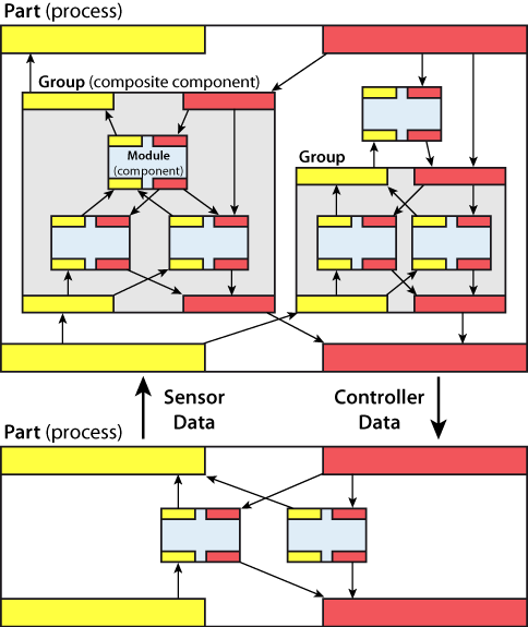
Similar to many other robotic frameworks (MCA2 in particular), Finroc applications are constructed from interconnected components. A significant set of all kinds of reusable components are available in finroc_libraries_* repositories (currently, only few of them are available on finroc.org). Similar to MCA2, the structural elements in Finroc applications are modules (basic components), groups (composite components) and parts (executables/processes).
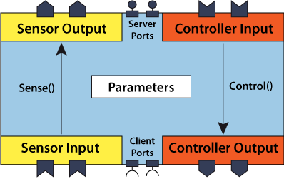
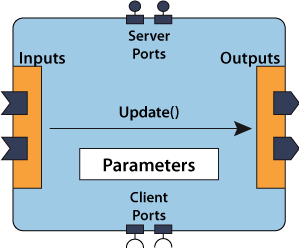
Modules are the basic application building blocks. Their interfaces are a set of ports. Often, these are data ports: Output ports are used to publish data, whereas Input Ports receive data. Edges are used to connect two ports. Ports can be connected n:m (however, typically only 1:n makes sense inside robotic applications). Modules with data ports connected by edges form a kind of data flow graph - which can be visualized with the finstruct tool.
Edges can connect components running on different systems just as well as components running inside the same process. This allows to easily create distributed systems.
Apart from data ports there are also rpc ports: Server ports provide an interface with remote procedure calls that client ports can connect to.
Finroc applications may consist of thousands of components. In order to maintain a clear application structure, modules can be placed in groups that have their own interface. Using groups, an application hierarchy is established.
Modules are typically assigned to thread containers. The thread inside the thread container will trigger any periodic update tasks continuously with a certain cycle time. It is, however, also possible to react to asynchronous events.
Similar to the MCA2 framework, Finroc distinguishes between sensor and controller data. Sensor data (yellow) flows upwards in application visualization. Controller data (red) flows downwards. Distinguishing between sensor and controller data in this way, supports clear application visualization and structure.
Finroc supports different component types. The SenseControlModule and SenseControlGroup are the respective component types from MCA2, extended by service ports. Apart from that, there are plain modules and groups or e.g. iB2C behaviours.
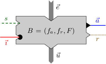
Create robot simulation group
As stated in the introduction, we will now create a simple simulation of a robot moving in a planar environment with a wall. It is equipped with two distance sensors and it can be destroyed if it hits the wall too hard.
The wall is built from (2, -∞) to (2, ∞).
It will be a very high-level implementation of a robot simulation. So we won't implement any modules for kinematics etc.
The robot simulation group will have two Controller Input ports: the velocity and angular velocity.
Sensor Output ports are the current position in the world coordinate system and two outputs from our simulated IR sensors: IR distance front and IR distance rear.
Creating the (empty) group
The simulation will consist of several modules. We will encapsulate all these modules in a single composite component - the simulation group. The group has its own interface - and the outside may only interact with the simulation using this interface.
The interactive finroc_create script is used to create code templates for all kinds of Finroc source files (edit /etc/content_templates.xml if you want to make changes to the default header). We will use it to create an empty group "Simulation":
Choose C++ => Finroc Projects => SenseControlGroup => leave Implementation File (cpp) selected and choose OK => crash_course => Select . => Enter Simulation => Enter This group realizes a simple simulation for a differential-driven robot. Press Ctrl+D (possibly twice) => Enter your name => OK
This will create gSimulation.h and gSimulation.cpp in your project directory. These files already contain some code and examples.
Open sources/cpp/projects/crash_course/gSimulation.h and locate the block where the ports are defined.
//----------------------------------------------------------------------
// Ports (These are the only variables that may be declared public)
//----------------------------------------------------------------------
public:

  tControllerInput<double> ci_signal_1;
This section defines the interface of your group to the outside.
Replace the example port with the ports we want to have for our group:
//----------------------------------------------------------------------
// Ports (These are the only variables that may be declared public)
//----------------------------------------------------------------------
public:
  /*! Desired velocity */
  tControllerInput<rrlib::si_units::tVelocity<>> velocity;

  /*! Desired angular velocity */
  tControllerInput<rrlib::si_units::tAngularVelocity<>> angular_velocity;

  /*! Position of our robot in the world coordinate system */
  tSensorOutput<rrlib::localization::tPose2D<>> pose;

  /*! Simulated distance sensor values to the front and to the rear */
  tSensorOutput<rrlib::si_units::tLength<>> ir_distance_front, ir_distance_rear;
The type in the brackets is the data type that will be transferred via this port. This can be any C++ type for which the stream operators for serialization have been overloaded (see Tutorials/Advanced/Suitable Port Data Types.
Note that we could simply use double as type for e.g. the velocity port. Using the data types from rrlib_si_units (see here), however, component interfaces are more clearly defined (and safer). Values are always in the SI base unit (e.g. meter for tLength). Calling Value() on any SI unit type returns the raw numeric value.
Note further that we use the type tPose2D from the rrlib_localization library. We need to add includes for all data types from external libraries (they belong in the External includes section in gSimulation.h):
//----------------------------------------------------------------------
// External includes (system with <>, local with "")
//----------------------------------------------------------------------
#include "rrlib/localization/tPose.h"
#include "rrlib/si_units/si_units.h"
Creating Modules
Main simulation module
Now, we will create the first module - for the main simulation. In the following, it is demonstrated how a module is is created.
Create a SenseControlModule named "MainSimulation" in sources/cpp/projects/crash_course in more or less the same way as we created the group. Comment: "This module simulates a differential-driven robot and two distance sensors".
Note, that the generated source files already contain various comments on what kind of code belongs where.
-
The module shall have the same interface as our group. Open
sources/cpp/projects/crash_course/mMainSimulation.hand replace the example ports with the same ports as in the group. -
Add the include
tPose.handsi_units.hagain. -
Below these ports, add some parameters:
  /*! Maximum acceleration of robot */
  tParameter<rrlib::si_units::tAcceleration<>> max_acceleration;

  /*! If the robot hits the wall with more than this speed, it is destroyed */
  tParameter<rrlib::si_units::tVelocity<>> destructive_collision_speed;

  /*! Maximum range of IR sensors */
  tParameter<rrlib::si_units::tLength<>> max_ir_sensor_distance;
- We need some internal variables for our calculations. They belong in the private area of the class (after the destructor which is located at the protected section):
//----------------------------------------------------------------------
// Private fields and methods
//----------------------------------------------------------------------
private:

  /*! Robot's current speed */
  rrlib::si_units::tVelocity<> current_speed;

  /*! Robot's current position and orientation */
  rrlib::localization::tPose2D<> current_pose;

  /*! Counts the number of spawned robots (internal) */
  uint robot_counter;

  /*! Info about last collision */
  rrlib::localization::tPose2D<> last_collision_pose;
  rrlib::time::tTimestamp last_collision_timestamp;
  bool last_collision_destructive;
Attention
Member variables must be initialized in the constructor - in the mMainSimulation.cpp. Otherwise, the variables with an elementary type will have an arbitrary/undefined value. Using an initializer list is the preferred way of initializing class members in C++.
Furthermore, we set some default values for the parameters.
//----------------------------------------------------------------------
// mMainSimulation constructor
//----------------------------------------------------------------------
mMainSimulation::mMainSimulation(core::tFrameworkElement *parent, const std::string &name) :
  tSenseControlModule(parent, name, false),
  max_acceleration(0.3),
  destructive_collision_speed(0.9),
  max_ir_sensor_distance(2),
  current_speed(0),
  current_pose(),
  robot_counter(0),
  last_collision_pose(),
  last_collision_timestamp(rrlib::time::cNO_TIME),
  last_collision_destructive(false)
{}
For convenience, we will import/use a namespace.
Attention
Namespaces should should never be imported in header files (.h and .hpp)!
//----------------------------------------------------------------------
// Namespace usage
//----------------------------------------------------------------------
using namespace rrlib::si_units;
The module's Sense() and Control() methods will be called regularly - every 40ms in this tutorial. It is important to ensure that the control flow does not get stuck inside these methods.
Replace the current Sense() method with this slightly clumsy simulation implementation (feel free to improve it). It is not important to understand the details of this particular implementation. You can just copy/paste it. Note that in this tutorial we do not use any existing Finroc components. Therefore, we need a little bit more code to get started and let the simulation do something somewhat interesting.
//----------------------------------------------------------------------
// mMainSimulation Sense
//----------------------------------------------------------------------
void mMainSimulation::Sense()
{
  tTime<> delta_t = scheduling::tThreadContainerThread::CurrentThread()->GetCycleTime();
  rrlib::time::tTimestamp now = rrlib::time::Now();

  // Calculate new speed
  const tVelocity<> cZERO_SPEED = 0;
  tVelocity<> desired_speed = velocity.Get();
  tVelocity<> new_speed = 0;
  if (desired_speed >= cZERO_SPEED)
  {
    new_speed = current_speed < cZERO_SPEED ? cZERO_SPEED : ((desired_speed < current_speed) ? desired_speed :
                std::min(velocity.Get(), current_speed + max_acceleration.Get() * delta_t));
  }
  else
  {
    new_speed = current_speed > cZERO_SPEED ? cZERO_SPEED : ((desired_speed > current_speed) ? desired_speed :
                std::max(velocity.Get(), current_speed - max_acceleration.Get() * delta_t));
  }
  tVelocity<> avg_speed = (current_speed + new_speed) / 2;
  current_speed = new_speed;

  // Calculate new orientation
  auto new_direction = current_pose.Yaw() + angular_velocity.Get() * delta_t;
  auto avg_direction = (current_pose.Yaw() + new_direction) / 2;

  // Calculate new coordinates
  tLength<> s = avg_speed * delta_t;
  current_pose.Set(current_pose.X() + s * avg_direction.Value().Cosine(), current_pose.Y() + s * avg_direction.Value().Sine(), new_direction);

  // Did we collide with the wall?
  typedef rrlib::localization::tPose2D<> tPose2D;
  tPose2D back_left = current_pose;
  back_left.ApplyRelativePoseTransformation(tPose2D(-0.2, 0.2));
  tPose2D back_right = current_pose;
  back_right.ApplyRelativePoseTransformation(tPose2D(-0.2, -0.2));
  tPose2D front_center = current_pose;
  front_center.ApplyRelativePoseTransformation(tPose2D(0.1, 0));
  tLength<> max_x = std::max(back_left.X(), std::max(back_right.X(), front_center.X() + tLength<>(0.2)));
  const tLength<> cWALL_X = 2;
  if (max_x > cWALL_X)
  {
    last_collision_pose = current_pose;
    last_collision_destructive = avg_speed > destructive_collision_speed.Get() || (-avg_speed) > destructive_collision_speed.Get();
    last_collision_timestamp = now;
    if (!last_collision_destructive)
    {
      current_pose.SetPosition(current_pose.X() - (max_x - cWALL_X), current_pose.Y());
      current_speed = 0;
      FINROC_LOG_PRINT(WARNING, "Robot collided with wall at a speed of ", avg_speed);
    }
    else
    {
      robot_counter++;
      current_pose.Reset();
      current_speed = 0;
      FINROC_LOG_PRINT(ERROR, "Robot crashed at a speed of ", avg_speed, " and was destroyed. Respawning. Destroyed Robots: ", robot_counter, ".");
    }
  }
  FINROC_LOG_PRINT(DEBUG_VERBOSE_1, "New robot position: ", current_pose);

  // Calculate sensor values
  tPose2D robot_in_2m = current_pose.Translated(rrlib::math::tVec2d(2, 0).Rotated(current_pose.Yaw().Value()));
  tPose2D robot_2m_back = current_pose.Translated(rrlib::math::tVec2d(-2, 0).Rotated(current_pose.Yaw().Value()));
  tLength<> front_distance = max_ir_sensor_distance.Get();
  tLength<> rear_distance = max_ir_sensor_distance.Get();
  double dx = fabs((robot_in_2m.X() - current_pose.X()).Value());
  if (robot_in_2m.X() > cWALL_X)
  {
    front_distance = (2 * (cWALL_X - current_pose.X()).Value() / dx);
  }
  if (robot_2m_back.X() > cWALL_X)
  {
    rear_distance = (2 * (cWALL_X - current_pose.X()).Value() / dx);
  }

  // publish updated values
  pose.Publish(current_pose, now);
  ir_distance_front.Publish(front_distance, now);
  ir_distance_rear.Publish(rear_distance, now);
}
Add the external include to the include section at the beginning of the .cpp file
//----------------------------------------------------------------------
// External includes (system with <>, local with "")
//----------------------------------------------------------------------
#include "plugins/scheduling/tThreadContainerThread.h"
As you probably noticed, the generated source files contain prose text with instructions (that won't compile) at places you should pay attention to, before using the module. The methods OnStaticParameterChange() and OnParameterChange() are such candidates. As we do not use them in this module, you can delete them completely (from the .h and the .cpp file). Also, delete the content of the Control() method.
Sensor noise simulation module
Now we will create a plain Module (no SenseControlModule) for simulating sensor noise. It will add a gauss-distributed random value to the numeric input. Call it "AddNoise". Comment: "Adds noise (a gauss-distributed random value) to the numeric input."
We create a plain Module instead of a SenseControlModule, because we cannot really say if the processed values in this module are always sensor data (in this tutorial we can, but let's say it will become a generic library module).
Open sources/cpp/projects/crash_course/mAddNoise.h and replace the example ports with:
//----------------------------------------------------------------------
// Ports (These are the only variables that may be declared public)
//----------------------------------------------------------------------
public:
  /*! Input value */
  tInput<rrlib::si_units::tLength<>> input;

  /*! Output value (= input value with added noise) */
  tOutput<rrlib::si_units::tLength<>> output;

  /*! Standard deviation for added noise */
  tParameter<rrlib::si_units::tLength<>> standard_deviation;
Note that this would be an ideal candidate for a template module - as hard-coding the port data type is not really pretty here. For reasons of simplicity, it is no template module in this tutorial.
Furthermore, we add two private variables for random number generation:
//----------------------------------------------------------------------
// Private fields and methods
//----------------------------------------------------------------------
private:
  std::normal_distribution<double> normal_distribution;
  std::mt19937 eng;
This requires an additional external include:
In the constructor (implemented in the mAddNoise.cpp file), we set the module's standard deviation to 0.05m.
//----------------------------------------------------------------------
// mAddNoise constructor
//----------------------------------------------------------------------
mAddNoise::mAddNoise(core::tFrameworkElement *parent, const std::string &name) :
  tModule(parent, name, false),
  standard_deviation(0.05),
  normal_distribution(0, 0.05),
  eng(1234)
{}
This module only has an Update() method to fill in. We want to add random noise to the input signal and publish the result - every cycle. Open the file mAddNoise.cpp and replace the contents of the Update() method with:
So afterwards, it will look like
//----------------------------------------------------------------------
// mAddNoise Update
//----------------------------------------------------------------------
void mAddNoise::Update()
{
   output.Publish(input.Get() + rrlib::si_units::tLength<>(normal_distribution(eng)));
}
Note
As noise is always to be added (not only if the input changes), we removed the if-block from Update().
When the parameter changes, we need to reinitialize the normal_distribution. Replace the existing OnParameterChange() implementation with:
//----------------------------------------------------------------------
// mAddNoise OnParameterChange
//----------------------------------------------------------------------
void mAddNoise::OnParameterChange()
{
  normal_distribution = std::normal_distribution<double>(0, standard_deviation.Get().Value());
}
OnParameterChange() is called by the framework, whenever one of the module's parameters change (and never concurrently to Update()).
Again, delete the obsolete code and prose fragments from the source files. (Please note: in contrast to the previous mMainSimulation, the OnParameterChange() method has to remain in the .h file, as we have given an implementation in the .cpp. Again, the OnStaticParameterChange() method can be deleted.)
Instantiate and connect modules
Now, we need to put such modules inside our group. We can do this either in source code or with a graphical tool (modifying XML structure information). We will do this in source code here. Currently, our group is empty.
The modules that we created should be instantiated in the group's constructor. Open sources/cpp/projects/crash_course/gSimulation.cpp and insert the following block into the constructor (gSimulation::gSimulation - inside the {}):
  // create modules
  mMainSimulation* main_sim = new mMainSimulation(this);
  mAddNoise* add_noise = new mAddNoise(this, "AddNoise Front");

  // connect some ports
  velocity.ConnectTo(main_sim->velocity);
  angular_velocity.ConnectTo(main_sim->angular_velocity);
  main_sim->pose.ConnectTo(pose);
  main_sim->ir_distance_front.ConnectTo(add_noise->input);
  add_noise->output.ConnectTo(ir_distance_front);
This will create the two modules and connect their ports. (We will instantiate and connect a second AddNoise module for the rear sensor later - graphically).
Furthermore, we need to include the two module types. (These belong in the internal includes section, because they come from the same project/repository)
//----------------------------------------------------------------------
// Internal includes with ""
//----------------------------------------------------------------------
#include "projects/crash_course/mMainSimulation.h"
#include "projects/crash_course/mAddNoise.h"
Create part
In Finroc, there are two ways to create an application that can actually be executed.
- Create a binary executable
- Create a
.finrocfile usingfinstructand execute it usingfinroc_run
We will create a binary executable here. When the finstruct tool is introduced in the next chapter, the second option is explained.
Create a part in sources/cpp/projects/crash_course and name it "CrashCourse" (Comment: "This part (program) executes a small robot simulation")).
Open sources/cpp/projects/crash_course/pCrashCourse.cpp. At the end, replace
with (we want to place our simulation group below the top-level thread container):
Then, set the main thread's cycle time to to 40ms (by replacing the existing line or changing the 50 to 40):
Furthermore, projects/crash_course/gSimulation.h needs to be included instead of projects/crash_course/mCrashCourse.h.
Furthermore we can rename the application's root element to "CrashCourse" by changing the string in the line where main_thread is created:
finroc::structure::tTopLevelThreadContainer<> *main_thread = new finroc::structure::tTopLevelThreadContainer<>("CrashCourse", __FILE__".xml", true, make_all_port_links_unique);
Finally, we need to tell our build system what it should build. Therefore we create a make.xml file in sources/cpp/projects/crash_course:
<?xml version="1.0" encoding="UTF-8" standalone="no"?>
<targets>
  <library>
    <sources exclude="pCrashCourse.cpp">
      *.cpp
    </sources>
  </library>

  <program name="finroc_crash_course">
    <sources>
      pCrashCourse.cpp
    </sources>
  </program>
</targets>
This builds a library libfinroc_projects_crash_course.so containing all our new components. Furthermore, a program called finroc_crash_course will be created. See Tutorials/Advanced/MakeBuilder for details on the make.xml file format.
Build Part
So now everything should be fine and we can start compilation. If Finroc is not installed on your system, this will take a moment.
(4 stands for the number of parralel build jobs. A value of number of CPU-cores + 1 is recommended)
If there are no errors, the build operation finishes with a done message.
Start Part
We can now start the part from a terminal / console (such as konsole, xterm, gnome-terminal). As all Finroc scripts and programs, the --help command line option lists the available already predefined options for starting the program:
The default options are fine.
Finstruct
Now, the part is running, but we do not see anything except of the console output yet. To inspect and interact with this part, we have the two tools fingui and finstruct.
Since our console running the part is blocked, we need to open another one. (In the new console we need to run source scripts/setenv in the Finroc directory again.)
Finstruct should be started by typing
At startup it asks where to connect to. localhost:4444 is fine.
Click on Simulation in the left tree. You should now see the structure of gSimulation group we just edited.
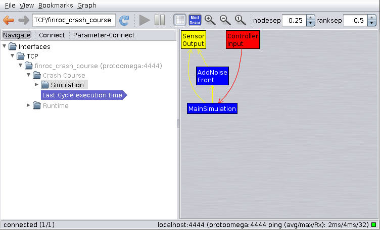
The tree view on the left can be used to navigate through the hierarchy of framework elements.
If you want, you can experiment with this tool. You should not worry about breaking anything. Since the part is hard-coded, it is always possible to restart it and everything should return to normal.
Inspect port and parameter values
Navigate to the AddNoise Front module's Outputs. The view will change and show the current value of the output port.
Now select the "AddNoise Front" module (type is mAddNoise', its name is "AddNoise Front" as defined in the code before) in the left tree and View->Port Data from the menu. This will show all the module's ports and its parameter.
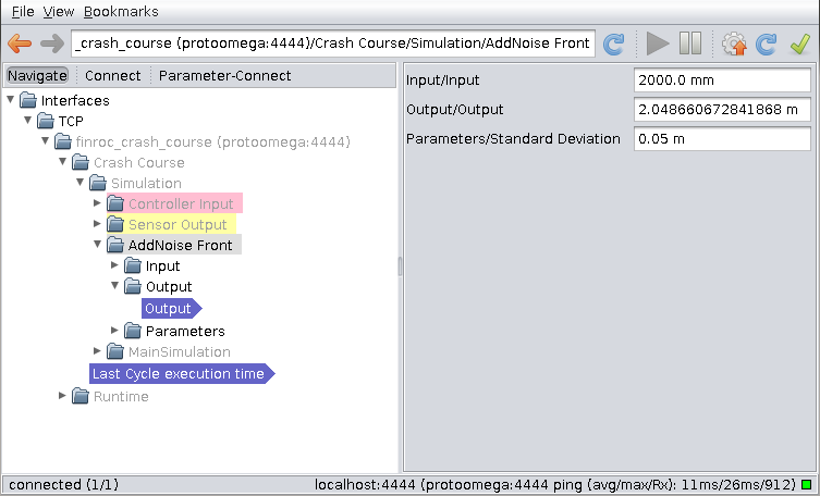
If you press Single Update (blue toolbar button on the right), the displayed port values will be updated once (currently, only Output will change). If you activate Auto Update, the port values will be updated regularly.
Deactivate auto-update and enter 5 m as Standard Deviation Parameter and press the green "Apply" button. Note, how the output value range changes (you need to update values again to see the effect).
Now enter 5 cm. Notably, this works (a nice side-effect of setting si_units in ports and parameters).
Now, set the view back to Auto Select in the View menu.
Graphically create and connect modules
So now we are going to create a second AddNoise module from within finstruct. Navigate back to see the structure of the gSimulation again (as in the first finstruct image) and select Connect mode in the tree toolbar.
If you click on the arrows in the diagram on the right, the corresponding connections are shown in the connection panel on the left.
Open the construction panel by clicking on the right-most icon in the toolbar (hammer and wrench).
Open Finroc Projects->Crash Course in the tree view on the right and select the AddNoise component type.
Change the name to AddNoise Rear in the bottom right panel.
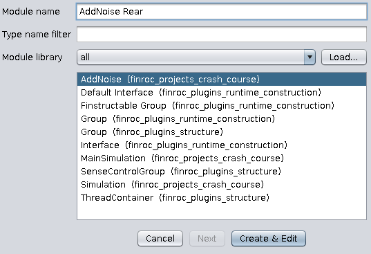
Click on Create to create the module.
Now we will connect it: In the component graph, click on Main Simulation and drag it to AddNoise Rear.
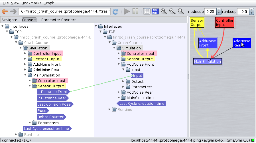
Both modules will be expanded in the trees on the left.
Now connect Ir Distance Rear with Input via dragging again.
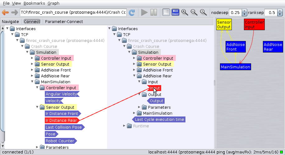
In the same way, connect AddNoise Rear/Output with Sensor Output/Ir Distance Rear (of the Simulation group!).
If you look at the ports of AddNoise Rear, you can see that it is already operating.
Now save the changes to our group by right-clicking on the gray area in the right diagram (with the blue, red, and yellow boxes) and selecting Save projects/crash_course/gSimulation.h.xml.
The result can be viewed in sources/cpp/projects/crash_course/gSimulation.h.xml.
<?xml version="1.0" encoding="UTF-8"?>
<Finstructable version="1703">
  <element name="AddNoise Rear" group="finroc_projects_crash_course" type="AddNoise">
    <parameters/>
  </element>
  <edge src="MainSimulation/Sensor Output/Ir Distance Rear" dest="AddNoise Rear/Input/Input"/>
  <edge src="AddNoise Rear/Output/Output" dest="Sensor Output/Ir Distance Rear"/>
</Finstructable>
Note, that such files may also be edited with a text editor.
If you stop the part (press ++ctrl-c++ in the corresponding console) and start it again (by executing finroc_crash_course), the AddNoise Rear module should be instantiated and connected.
Graphically create a part
As mentioned earlier, parts can also be created using finstruct.
Terminate the finroc_crash_course part.
Make sure, the $FINROC_PROJECT_HOME environment variable is set to $HOME/finroc/sources/cpp/projects/crash_course. You will probably have to call
once. You only need to add -p if you want to change the current project.
Changing the project is important so that the CrashCourse.finroc file containing the part will be loaded from and saved relative to the project directory.
.finroc files can be instantiated and executed using the finroc_run command. If the file does not yet exist, it will be created on saving.
Since $FINROC_PROJECT_HOME/CrashCourse.finroc does not exist yet, an empty part will be loaded.
In finstruct right-click (on the gray diagram/graph area) and select Create Element.... Our modules are not loaded yet. Therefore, click on Load... and double-click on finroc_projects_crash_course. The same can also be done with the hammer and wrench side bar which was introduced before.
Select the component Simulation (finroc_projects_crash_course) and click on Create & Edit, commit the dialog "Edit Static Parameters of Interfaces..." which opens with "Apply & Close".
Now, we have the same part.
If you right-click and save (Save "CrashCourse.finroc"), the file $FINROC_PROJECT_HOME/CrashCourse.finroc will be written (note that Crash Course needs to be selected in the tree view for this option appear. Depending on where you are navigating, options for either saving the group or the part are available).
You can see in the part's command line output where the file was saved.
FinGUI
Now, we will actually interact with our part using a graphical user interface.
GUI files, as well as config files and all other non-finroc code, is typically stored in an etc folder below our project directory.
Start the gui.
You will see an empty canvas where GUI widgets can be placed.
The FinGUI allows to select your preferred Look & Feel in the Edit-menu. Here's a brief summary on the default setting ("Office-like"):
- Select widget: Ctrl + left mouse button or select with a box (you can drag it by clicking on empty space and moving the mouse over the widgets)
- Change widget properties: Right-click on a selected widget
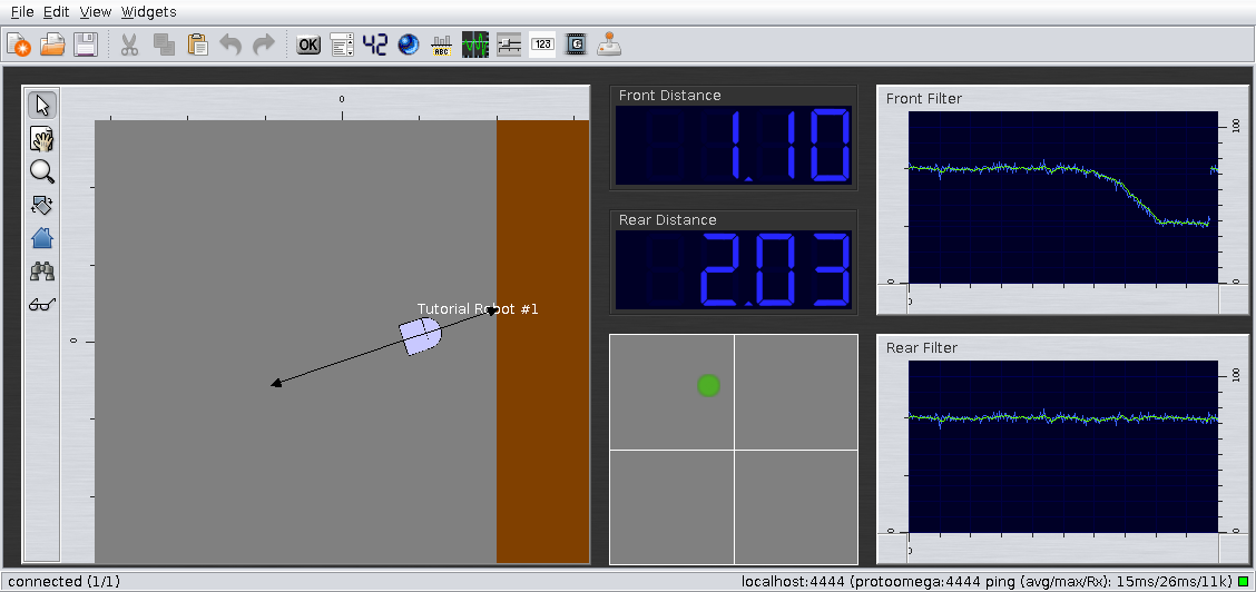
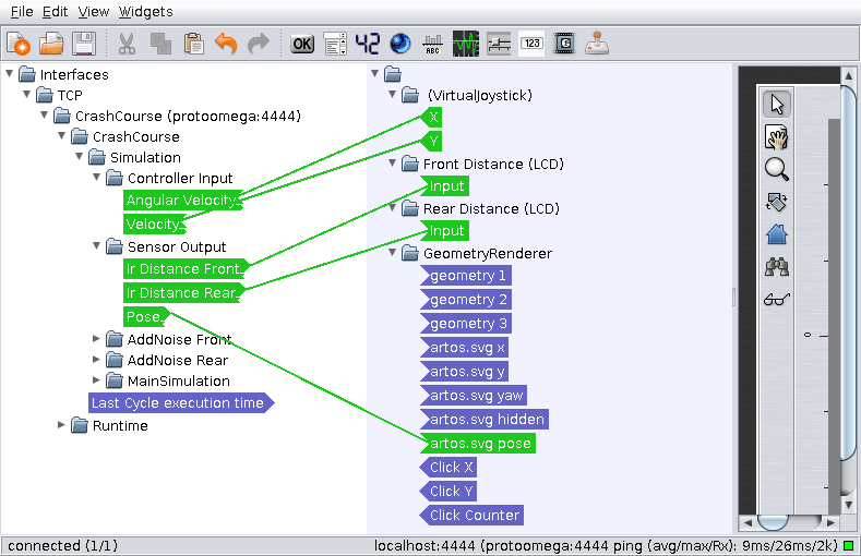
Create a GeometryRenderer, a VirtualJoystick, and two LCD numeric displays. You can assign labels to the LCDs in their properties dialog.
Download this .svg file and add it to the map objects in the GeometryRenderer properties.
As the coordinates are in mm, select artos.svg, press Edit..., and set the scale to 0.001.
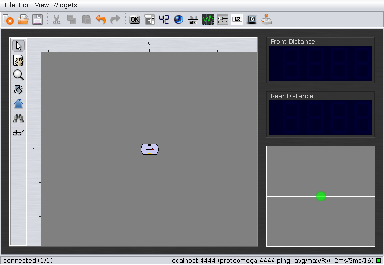
Furthermore, you need to invert the X axis of the virtual Joystick: X Left should be 1 and X Right should be -1.
Select File->Connect->TCP from the main menu and accept localhost:4444.
Now click on View->Connection Panel in the menu to open the connection panel you should already be familiar with from finstruct.
Connect the widgets in this way:
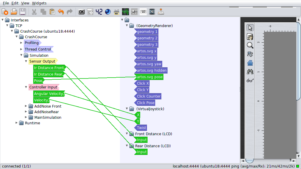
Now save the gui to your project's etc folder.
You can now experiment with the application you just built.
Component-defined visualization using tCanvas2D
Often, it is helpful to visualize the state of a component (see Tutorials/Intermediate/Component-Defined Visualization). The class tCanvas2D provides a flexible and powerful solution for this purpose.
The visual representation of the simulation in the geometry renderer is currently very basic. We will (re)use the visualization also in the GUI.
Add a dedicated visualization output port to mMainSimulation.h:
  /*! Visualization output */
  tVisualizationOutput<rrlib::canvas::tCanvas2D, tLevelOfDetail::ALL> visualization;
The include for tCanvas2D needs to be added:
The visualization will also be created in the Sense() method. When using dedicated visualization outputs, always check whether they are connected before operating on them.
The following code illustrates how geometry can be drawn to the canvas objects and how it can be published via ports (add it at the end of Sense()):
  if (visualization.IsConnected())
  {
    // visualize using tCanvas2D
    // obtain buffer
    data_ports::tPortDataPointer<rrlib::canvas::tCanvas2D> canvas = visualization.GetUnusedBuffer();
    canvas->Clear();

    // Draw wall
    canvas->SetFill(true);
    canvas->SetColor(128, 64, 0); // brown
    canvas->DrawBox(2, -1000, 2000, 2000);

    // Draw Robot Text
    canvas->Translate(current_pose.X().Value(), current_pose.Y().Value());
    canvas->SetColor(255, 255, 255);
    char robot_text[128];
    snprintf(robot_text, 128, "Tutorial Robot #%d", robot_counter + 1);
    canvas->DrawText(0.0, 0.28, robot_text);
    canvas->ResetTransformation();

    // Draw Robot
    canvas->Transform(current_pose);
    canvas->SetEdgeColor(0, 0, 0);
    canvas->SetFillColor(200, 200, 255);
    canvas->DrawEllipsoid(0.1, 0.0, 0.4, 0.4);
    canvas->DrawBox(-0.2, -0.2, 0.3, 0.4);
    canvas->ResetTransformation();

    // Indicate Collision
    rrlib::time::tDuration since_last_collision = rrlib::time::Now() - last_collision_timestamp;
    if (since_last_collision < std::chrono::milliseconds(2000))
    {
      canvas->Translate(last_collision_pose.X().Value(), last_collision_pose.Y().Value());
      double time_factor = 1.0 - (std::chrono::duration_cast<std::chrono::milliseconds>(since_last_collision).count() / 2000.0);
      canvas->SetAlpha(static_cast<uint8_t>(255.0 * time_factor * time_factor));
      canvas->SetColor(last_collision_destructive ? 255 : 50, 50, last_collision_destructive ? 50 : 255);
      canvas->DrawText(0.0, 0.0, last_collision_destructive ? "KABOOM!" : "Plonk");
    }

    visualization.Publish(canvas);
  }
Build the project and restart the part.
Remove artos.svg from the geometry renderer widget of the GUI and connect the module's visualization output instead.
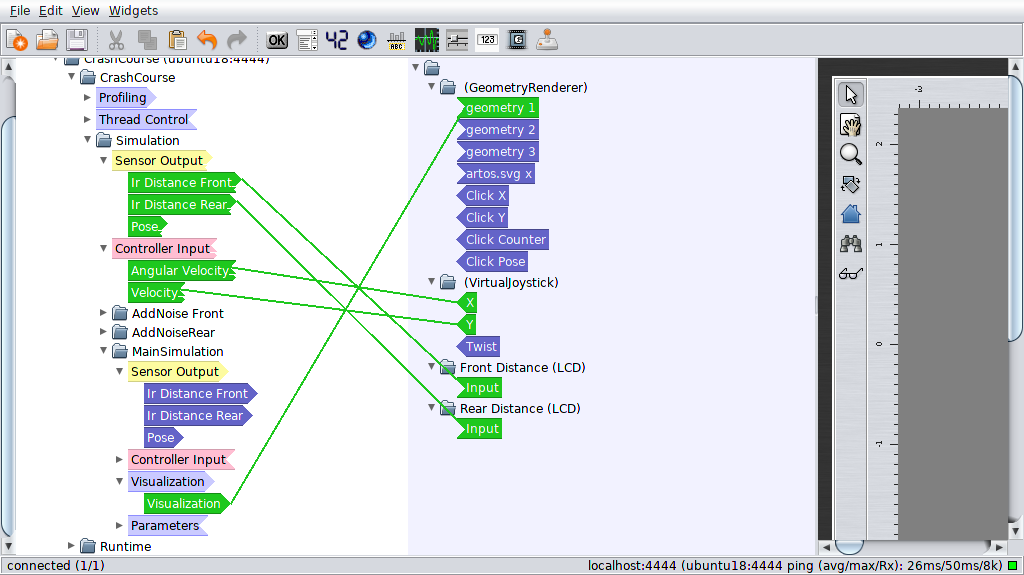
You should be able to observe how each of the objects in the module's source code are drawn.
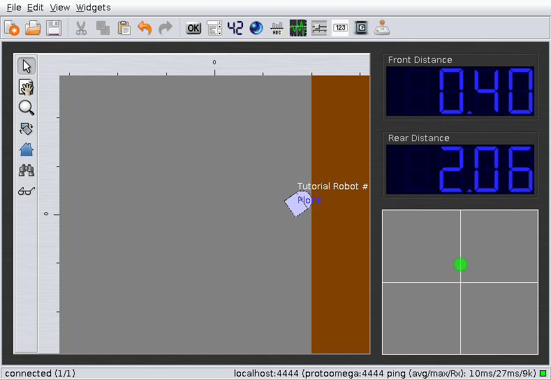
Parameters and config files
Parameters' default values in Finroc applications can also be set via config files.
Note that parameters and config files are an area, which we plan to significantly improve in the near future. Especially the graphical tool support is still in an experimental and very basic state.
Nevertheless, let's create a simple config file fragile_bot.xml in sources/cpp/projects/crash_course/etc with the following content:
<?xml version="1.0" encoding="UTF-8"?>
<root>
  <value name="noiselevel">15 cm</value>
  <node name="some structural element">
    <value name="destructive_collision_speed">0.1</value>
  </node>
</root>
Now start the part with this config file:
In finstruct, navigate to the simulation group and select "Parameter-Connect" mode from the tree toolbar.
You can now see the config file entries on the right. They can be connected to the parameters. Connect the Standard Deviation Parameter of both AddNoise modules to noiselevel. Also connect the main simulation module's Destructive Collision Speed parameter.
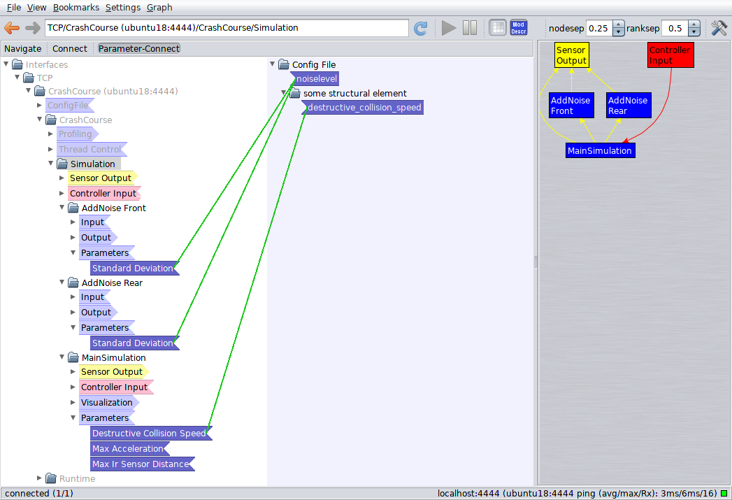
Save the part (CrashCourse.finroc).
(You might notice some new parameter entries in the .finroc file.)
This way, it is possible to create different configurations for the same application.
If you prefer to attach parameters to config file entries in source code, you could, for instance, add the following line to the constructor of gSimulation.cpp instead:
main_sim->destructive_collision_speed.SetConfigEntry("some structural element/destructive_collision_speed");
It is furthermore possible to set a (default) value from source code:
Set parameters from the command line
It is also possible to configure parameters to be read from the command line. However, this is not yet possible from finstruct.
Open the CrashCourse.finroc file and add cmdline="front-noise" to the front noise parameter:
  <parameter_links>
    <element name="Simulation">
      <element name="AddNoise Front">
        <parameter name="Standard Deviation" config="/noiselevel" cmdline="front-noise"/>
      </element>
You can now see, that a new command line parameter has been added:
Exercises
Up to this point, you completed a Finroc crash course. The many topics that are covered might seem a little overwhelming and confusing at first - especially as several ways of doing the same thing are presented. As experience shows, however, things become much easier as you continue using Finroc. If you had particular difficulties completing one of the steps above, we are always thankful to receive a hint.
In order to deepen your knowledge on the topics covered in this tutorial, you can try to do the following exercises by yourself.
Add a robot control group and implement filter
Add a SenseControlGroup "Control" to the part. To keep the project directory tidy, use a subdirectory control (a subdirectory for simulation components could have been added as well). It is supposed to contain the robot control system. Add Sensor Input ports for the simulation's Sensor Outputs - and Controller Output ports for the simulation's Sensor Inputs. Add the control group to the part and connect it.
Implement a simple module (mNoiseFilter) to reduce the noise in the distance sensor signals. Structurally, it is somewhat similar to the one that adds the noise. Of course, it needs to do something different in Update().
It is part of the robot control, so instantiate and connect it there.
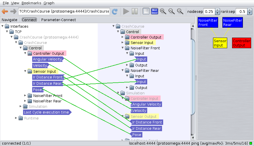
A simple filtering approach for this module is sufficient (e.g. sum up the last 5 values and calculate the arithmetic mean).
If you need a list - similar to Java's ArrayList - you could try std::vector.
Visualize distance sensor values
Modify mMainSimulations visualization so that the sensor values are visualized using the Canvas2D (possibly as lines).
Note that the simulated sensors measure the distance from the center of the robot.
